Valve Symbols in P&ID Ball Valve, Relief Valve and more
Here is a list of symbols for various types of valves used in process industry. Angle Blowdown Valve Angle Globe Valve Angle Valve Angle Valve Hand Operated Auto Circulation Valve Back Pressure Regulator Balanced Diaphragm Gate Valve Ball Valve Ball Valve Normally Closed Bleeder Valve Butterfly Valve Check Valve 01 Check Valve 02 Control Valve
Fire Symbol, Valve, Relief Valve, Safety Valve, Pressure, Faucet Handles Controls, Plumbing
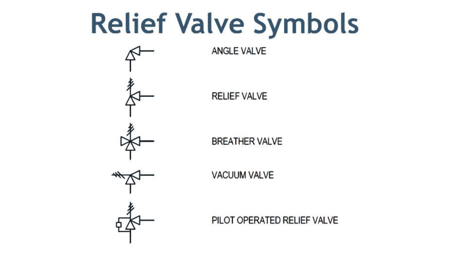
The main types of safety valves are identified by symbols. Therefore, there is not only one, but several safety valve and safety valve symbols. They are often shown on safety valves or their packaging. In addition, they are used in technical drawings and schematics as well as system sketches - for example, in the description of DIN standards.
Valve Symbols in P&ID Ball Valve, Relief Valve and more
A gate valve will open or cut off the flow of water through a pipe. They typically have a wheel handle that gets turned to operate the metal disk that blocks the flow. Its symbol looks like the outline of a bowtie with two straight lines crossing each other to form an "X". Then two vertical lines connect the ends to create an enclosed shape.
Safety valve symbol icon Royalty Free Vector Image
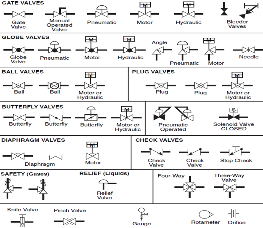
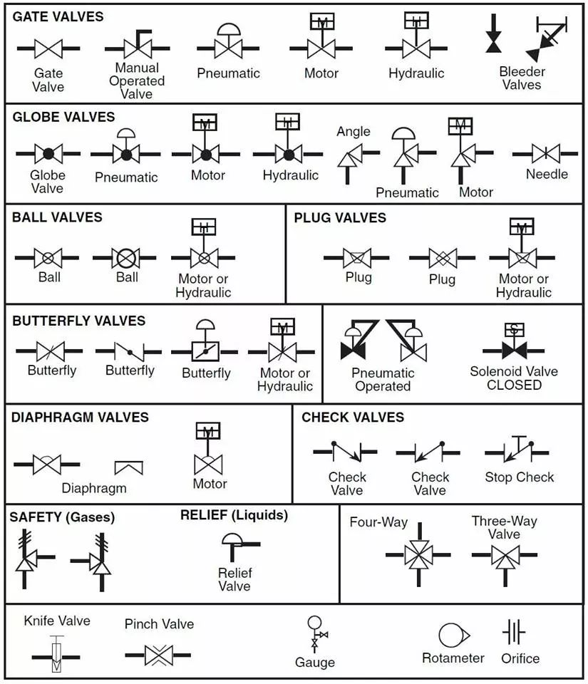
SYMBOLS VALVES valve is a mechanical device that controls the flow of fluid and pressure within a system or process. valve controls system or process fluid flow and pressure by performing any of the following functions: Stopping and starting fluid flow Varying (throttling) the amount of fluid flow Controlling the direction of fluid flow
Control Valve Symbol
The symbology for the identification of the measurement and control instrumentation on the flow and process diagrams and on the P&ID (Piping & Instrument Diagram), commonly called P&I (Piping & Instrumentation), is generally compliant with the Standard ISA (Instrumentation Society of Automation) identified as S.5, that is composed of identificat.
Valve Sign Symbols The Engineering Concepts
It will usually feature two blowdown rings, and is identified by a National Board 'V' stamp. ASME VIII valve - A safety relief valve conforming to the requirements of Section VIII of the ASME pressure vessel code for pressure vessel applications which will open within 10% overpressure and close within 7%. Identified by a National Board 'UV' stamp.
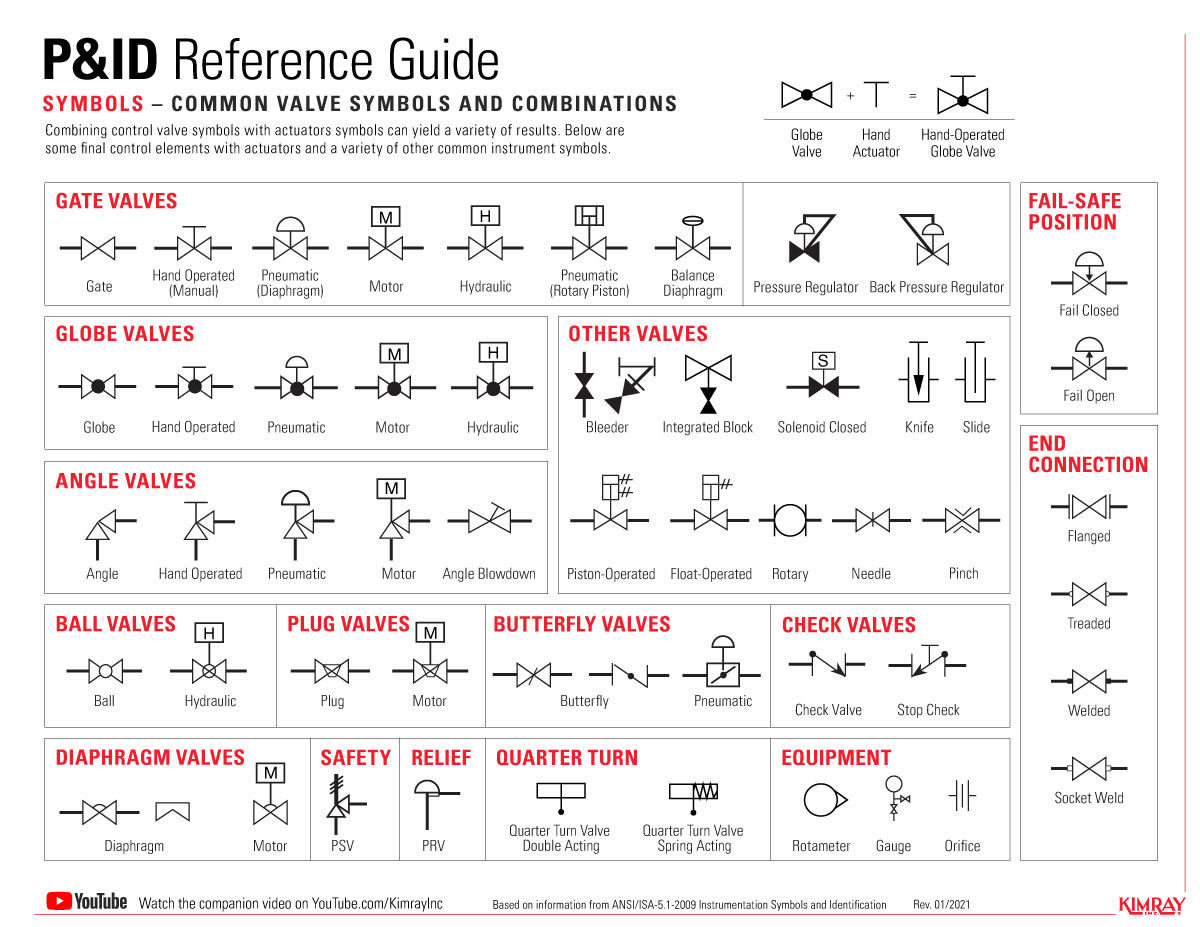
The Most Common Control Valve Symbols on a P&ID Kimray
Types of valves with P&ID symbols. A valve is an element in a piping system that regulates the flow. A rotary valve turns only at 90°. Linear valves operate when the stem is vertical, and the packing box is above. Self-actuated valves keep set-point pressure in pipelines within predetermined ranges.
Control valve symbol icon Royalty Free Vector Image
by Editorial Staff Typical P&ID arrangement - Pressure Safety Valves The sample drawing presented here represents a typical arrangement generally used to represent safety valves or relief valves on P&ID. First of all a proper safety valve symbol should be selected to represent the control valve as per the project standards.
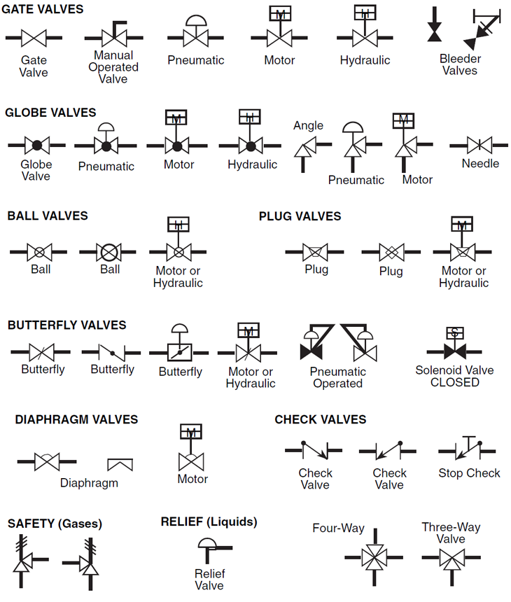
Valve Symbols for P&IDs The Engineering Concepts
Equation 6 : pressure safety valve required discharge area in the case of steam. The correction factor K N can be calculated the following way : K N = 1 if P 1 ≤ 10339 kPa abs. K N = (0.02764*P 1 -1000) / (0.03324*P 1 -1061) if 10339 ≤ P 1 ≤ 22057 kPa abs. Ksh = superheat steam correction factor.
Symbol Logo Safety valve , symbol transparent background PNG clipart HiClipart
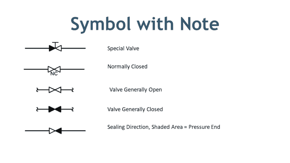
There are two types of valve symbols — first, generic symbols, and second, a symbol with a modifier. Generic symbols will tell you that there is a valve in the line, but they will not tell you about the types of the valve. Whereas the valve symbol with modifier will tell you the type of valve used in the pipeline. Generic symbols of Valves
The Most Common Control Valve Symbols on a P&ID Kimray
IEC Symbols; JIC / NFPA Symbols; Koyo; DirectLOGIC 05/06 PLC AIO Modules; DirectLOGIC 05/06 PLC AIO Modules - Layout;. Angle Spring Safety Valve. Category: P&ID Valves. Stencil: P&ID ISO Valves. Tags: P&ID, Piping, Instrumentation, Instruments, Valves, Angle, Safety, Spring. Edit SVG PNG JPG DXF DWG.
Symbol Logo Safety valve, symbol, angle, white, text png PNGWing
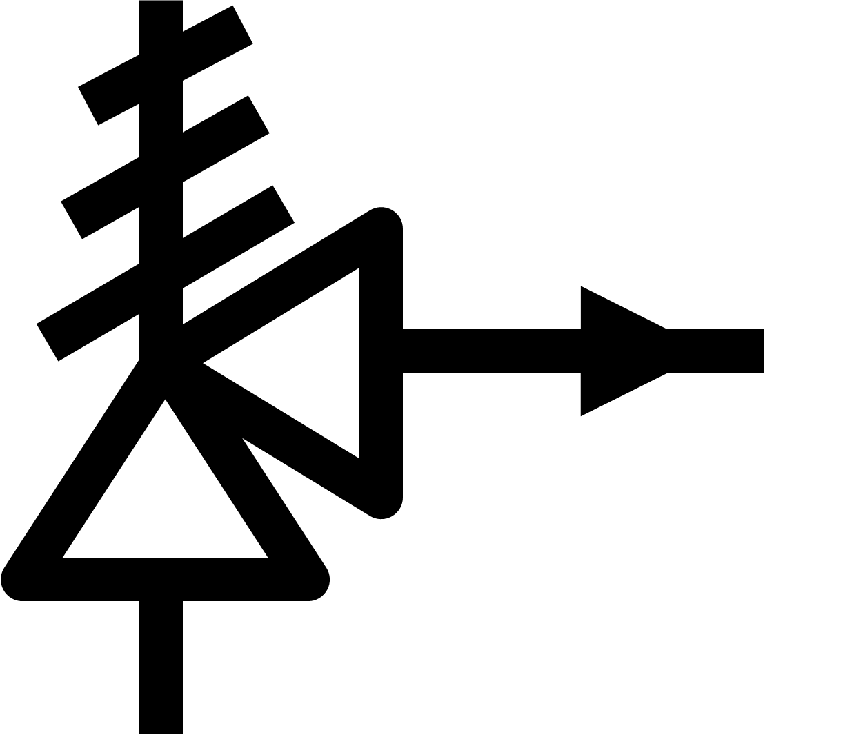
A pressure relief valve is a NC (normally closed) type safety valve which operates when system pressure increases above a maximum working pressure. The normally closed position is indicated by the arrow away from the center line. The dashed line indicates that the system pressure acts against spring force for valve actuation.
The Most Common Control Valve Symbols on a P&ID Kimray
Some of the most common 2-way valve symbols are ball valves, butterfly valves, plug valves, gate, valves, etc. Examples of these symbols can be found further down in this article. Figure 2: A gate valve with the direction of flow running from left to right. 3-way and 4-way valves

Valve Symbols in P&ID Ball Valve, Relief Valve and more
P&ID refers to a very detailed visual representation of all the components involved in the process flow. They include the vessels, piping, control valves, instrumentation, equipment, and other components involved in the plant process. The piping and instrumentation diagram is a very critical illustration of the stages of the plant process system.
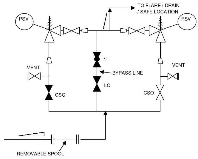
P&ID Guidelines for Pressure Safety Valves Inst Tools
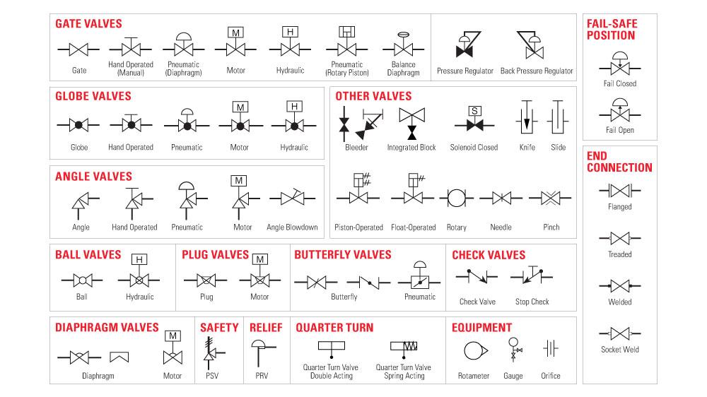
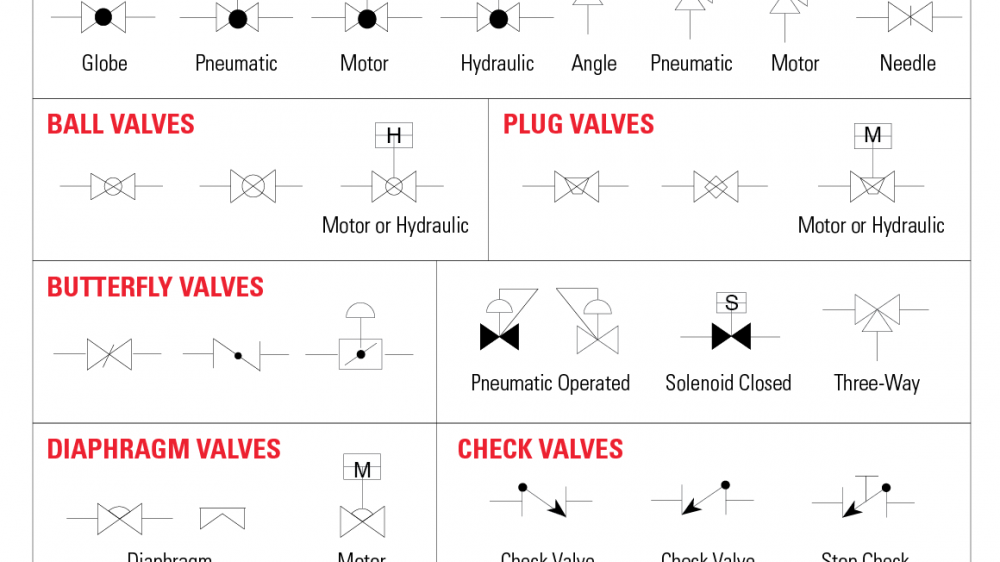
Symbols include: gate valve symbol globe valve symbol ball valve symbol plug valve symbol butterfly valve symbol diaphragm valve symbol check valve symbol DOWNLOAD THIS CHART An engineer may also include specific details below the control valve symbol. These details may include the size, function, pressure rating, and connection type of the valve.
swing check valve symbol Swing check valve
DIAPHRAGM VALVES SAFETY RELIEF QUARTER TURN BUTTERFLY VALVES GATE VALVES FAIL-SAFE POSITION GLOBE VALVES OTHER VALVES ANGLE VALVES BALL VALVES PLUG VALVES Diaphragm Gate Globe Pneumatic Motor. SYMBOLS - COMMON VALVE SYMBOLS AND COMBINATIONS Combining control valve symbols with actuators symbols can yield a variety of results. Below are